Debug TinyGo code running on Raspberry Pico using VSCode
Happy new year! Wow, almost exactly 3 years ago since I wrote something, this is embarrassing. I guess there’s nothing better than starting to write again on the 1st of the year.
Let’s talk about how to use VSCode to debug Go code running on a raspberrypi pico microcontroller!
Code for this article can be found in this git repo
TLDR; just show me how to do it!
Around 2020 I started learning and also using Go professionally. I like how simple it is to start writing and understanding Go code, so one of the questions that popped up at the time was if it was possible to compile it to microcontrollers such as atmel or arm devices. TinyGo project addresses exactly the port to these microcontroller architectures, while still making it possible to use the garbage collected memory model. It uses LLVM instead of outputting C code and then compiling it to binaries, which in practice also creates smaller code optimized for these processors.
I started experimenting with the Raspberry pico board which was released in 2021 by the Raspberry foundation. I quickly realized it was going to be very tedious to investigate issues and bugs, since all I could do was printing text to the serial interface via logger.Debug("code reached here 1") statements. Far from ideal.
Picoprobe to the rescue! With picoprobe, you can use another raspberry pico as a SWD (Serial wire debugger), and navigate through code step by step as it’s executing on the board.
Another great advantage of using picoprobe is that the deployment of compiled binaries is also much easier! Instead of the traditional process, which involves building the binary, physically pressing the bootsel button on the board to enable the upload of the new compiled binaries, and then transferring the new compiled file to the board, all these steps can be consolidated into a single operation using the debugger pico board. This entire process can be seamlessly integrated into a single VSCode debug configuration.
Is it perfect? No. There are some things which are still a bit broken for me. For example, it’s not always possible to set watches on certain variables; some break points are also being ignored. Aside from that, most of it works and you even get access to the board’s memory from within the IDE.
As a side note, please be aware that everything discussed here assumes you are using Linux and have some familiarity with Go.
Let’s start!
Software needed
TinyGo
Install TinyGo by following the offical docs.
Go
Install a compatible version. While TinyGo strives to comply as much as possible with the latest versions of Go, it may fall behind by one or two major versions as TinyGo catches up with new developments in Go.
For ease of switching between different available versions, I recommend using Go Version Manager.
Check the compatibility matrix and install a compatible version.
GDB and OpenOCD
GDB setup
GDB enables us to stop programs at any specific line, display variable values, and determe where errors occurred. For Debian based distributions, gdb-multiarch should work just fine.
1
sudo apt install gdb-multiarch
OpenOCD setup
For OpenOCD, which is what interfaces with the hardware debugger running on the picoprobe, there is an openocd linux package available which did not work for me. When I attempted using it, starting the debug session resulted in an unknown parameter error.
Raspberrypi pico’s Getting started documentation (Appendix A: Build OpenOCD, page 60) contains instructions to build and install from their version of this software:
1
2
3
4
5
6
7
8
9
mkdir -p ~/pico
cd ~/pico
sudo apt install automake autoconf build-essential texinfo libtool libftdi-dev libusb-1.0-0-dev
git clone https://github.com/raspberrypi/openocd.git --branch rp2040 --depth=1
cd openocd
./bootstrap
./configure
make -j4
make install
Important (1)!: for OpenOCD to be able to interface with the USB device, the logged in linux user needs to be part of groups dialout and plugdev. You can check your groups with the groups command
1
groups
Important (2)!: After having built and installed OpenOCD, you might need to copy an udev rules file to your system. Reloading the rules after adding the file might also be needed.
1
2
sudo cp ~/pico/openocd/contrib/60-openocd.rules /etc/udev/rules.d/
sudo udevadm control --reload-rules
VSCode
Plugins
Install VSCode plugins cortex-debug, go, and tiny-go. Another nice-to-have is the serial-monitor plugin, which allows you to read output from the boards’ serial interface. It is not necessary for this tutorial though.
Hardware setup
You will need to have 2 pico boards. The first board will run the SWD software, while the second board will run your code.
Upload picoprobe firmware
Download the picoprobe firmware and upload it to the first board (the one that will be connected to your PC via USB cable)
Wire boards together
On a breadboard, connect following wires as shown in the picture:

For further details, reference the Getting started documentation (Appendix A: Using Picoprobe, page 60)
Project
Set up a new repo to start your project.
1
2
3
4
5
6
7
8
9
10
11
12
13
14
15
16
17
18
19
20
21
22
23
24
mkdir vscode-debug
cd vscode-debug
git init
go mod init vscode-debug
echo "package main

import (
	\"machine\"
	\"time\"
)

func main() {
	led := machine.LED
	led.Configure(machine.PinConfig{Mode: machine.PinOutput})

	for {
		time.Sleep(time.Second)
		led.High()
		time.Sleep(time.Second)
		led.Low()
	}
}" > main.go
mkdir svd
curl https://raw.githubusercontent.com/raspberrypi/pico-sdk/master/src/rp2040/hardware_regs/rp2040.svd -o svd/rp2040.svd
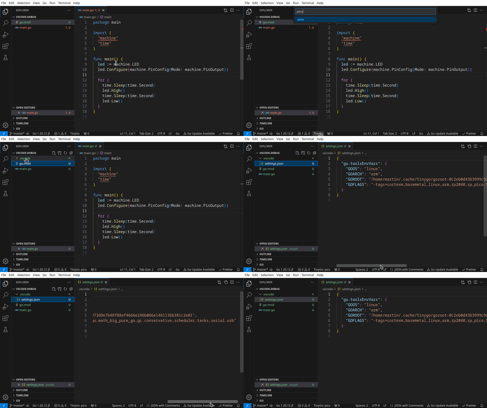
Open the project code in VSCode. The machine import will probably be broken. This is because each microcontroller will need a different implementation of the machine package, which will be chosen by the target build flag at compile time. Since no target was chosen yet, VSCode will not be able to link to the correct implementation. To fix this, configure the target with the help of the TinyGo VSCode plugin installed earlier.

Next, create two files in the .vscode folder. The first one will be instructing how to build the binary before it can be deployed to the board. Create a file named tasks.json with the following content:
1
2
3
4
5
6
7
8
9
10
11
12
13
14
{
  "version": "2.0.0",
  "tasks": [
    {
      "label": "build pico",
      "type": "shell",
      "command": "mkdir -p build && tinygo build -o build/out.elf -target pico -size short -opt 1 main.go",
      "group": {
        "kind": "build",
        "isDefault": true
      }
    }
  ]
}
The command attribute instructs how to compile the code with the -target pico flag, which tells the compiler to use the correct machine package. The second to be created will be the launch.json configuration, which will be listed in VSCode’s launch configuration dropdown.
1
2
3
4
5
6
7
8
9
10
11
12
13
14
15
16
17
18
19
20
21
22
23
24
{
  "version": "0.2.0",
  "configurations": [
    {
      "name": "Debug on Pico",
      "type": "cortex-debug",
      "servertype": "openocd",
      "request": "launch",
      "runToEntryPoint": "main.main",
      "executable": "${workspaceRoot}/build/out.elf",
      "configFiles": [
        "${env:HOME}/pico/openocd/tcl/interface/cmsis-dap.cfg",
        "${env:HOME}/pico/openocd/tcl/target/rp2040.cfg"
      ],
      "openOCDLaunchCommands": ["adapter speed 5000"],
      "preLaunchTask": "build pico",
      "showDevDebugOutput": "raw",
      "gdbPath": "/usr/bin/gdb-multiarch",
      // this had to be specified on linux otherwise the error dumps from OpenOCD did not work properly
      "objdumpPath": "/usr/bin/objdump",
      "svdFile": "${workspaceRoot}/svd/rp2040.svd"
    }
  ]
}
There are a few things to observe here: the configuration assumes you have downloaded the source code for OpenOCD into ~/pico/openocd. If you haven’t, please adjust the path accordingly, since it references 2 important files which are needed by OpenOCD to correctly interface with the SWD device (your picoprobe), namely cmsis-dap.cfg and rp2040.cfg.
Additionally, notice the svdFile attribute; an SVD file is an XML file which describes all registers and memory addresses present in a CPU in a standardized format. For the rp2040 processor (which is the processor unit used in a raspberry pi pico), the SVD file can be found in the pico-sdk repository, which was already conveniently downloaded while setting up the project in the beginning of this section
gdbPath was also configured to point to gdb-multiarch binary, since it normally points to arm-none-eabi-gdb.
Running the project
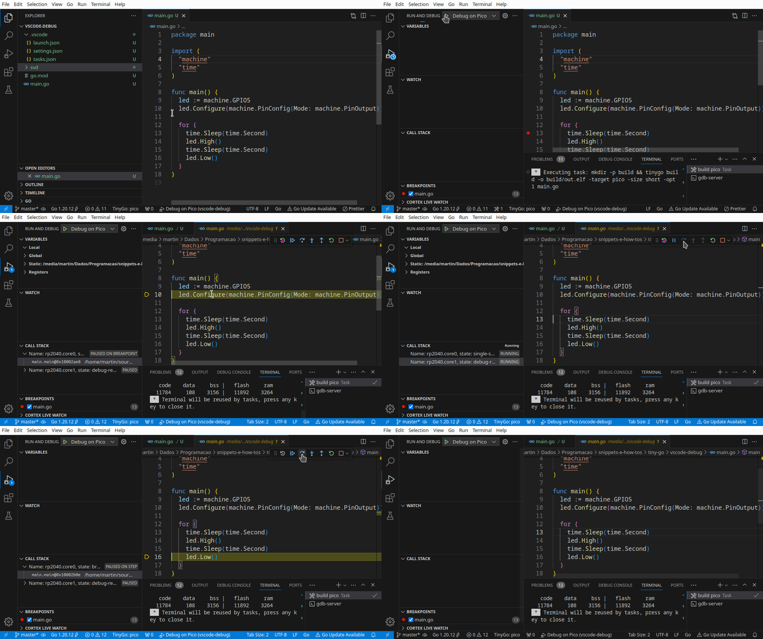
Double - nay, triple - check your wiring. I take no responsibility for fried computers, proceed at your own risk :). Connect the board to the computer via USB. If everything went well, it should now be possible to step through the code executing on the board from within VSCode!

Side note: in the demo above you’ll see me referencing GPIO5 as the LED pin in the code. This choice stems from the fact that I am using a pico W, the variant equiped with a Wifi chip. On these boards, the onboard LED is controlled via this Wifi chip. At the time of writing of this article, no official driver for the Wifi controller exists for TinyGo. Therefore, I just added an external LED to that GPIO.
 (Ignore the green wire: it’s not connected to anything).
Happy debugging!